


[ad_1]
I have to confess that I am no expert when it comes to controllers, and when I find someone who has a lot of experience and is honest about the benefits and drawbacks of any given model of controller, I want to hear what that tech has to say.
There are some very good products out there, but if every manufacturer says that their controller is the best, and never tells you why (or they fail to mention any particular weaknesses that it may have) then we can’t make an educated choice.
The reason these tech details are important is because some of the issues are something that we can fix ourselves, and other issues are completely integrated into the design. Plus, most builders don’t have an unlimited budget, so an affordable component that is “fixable” might sometimes be the best option.
I recently stumbled across a youtube channel where they do teardowns of popular EV components, and they spell out the raw data on the guts, both the good and the bad. It’s by Richard, and called “EV Components review (De-bodgery).
I found his channel looking for info on controllers, and he has quite a few of those. The one in particular that caught my eye is the good review on the Votol EM-150. I pay no attention to someone who says “this is good”, unless they can show me how its different, compared to the one they say is bad….or…I am annoyed of they only tell us the good parts, and leave out glaring weaknesses.
His tear-down is a 20-minute video of the Votol EM-150 being pulled apart and described. I’ll place a concise index at the end of the article of the pluses and minuses, with the video link at the bottom.
______________________________________________
First, the cover
This may be boring and unimportant, but the cover is not made from the common ABS plastic, its made from 30% glass (fiber) filled polyester. This is the same type of stuff that’s used in the bodies of high-end cordless tools.

The colored silicone-rubber insulating grommets are only held in by friction, and do provide some water resistance from splashing or a light rain, but this tech removed them, smeared some clear silicone on them and re-inserted them for a much better seal against water.
The screws that hold the cover onto the frame of the controller get a down-vote for passing through the aluminum heat-sink plate and screwing into plastic. It works, and it holds OK, but if you remove the cover and re-attach it a few times, I don’t think these self-tapping screws would hold as well over time. Other controllers in this price range have brass inserts and machine screws with lock-washers, so they could be cycled dozens of times with no problems. I’ve never had one of these in my hands, so it may be possible to drill out the posts a hair, and epoxy-in some brass threaded inserts.
Richard also pointed out that the edge-seal on the cover is quite good.
______________________________________________
The Electronic Components
This controllers brain is the “Central Processing Unit”, and this one uses the STM32F103 from ST-Microelectronics, which is a name-brand CPU. This CPU is powerful enough to handle “Field Oriented Control” / FOC, but…this controller does not use FOC, apparently because that would require upgraded hardware, including an individual shunt on each of the three phase wires.

One of the things that caught my ear is when Richard mentioned that the FET’s are high-end FET’s rather than hot-running generic units. They are the MDP10N027’s from Magna Chip. He even mentioned that these are his favorites, and he has used them many times on his personal projects.
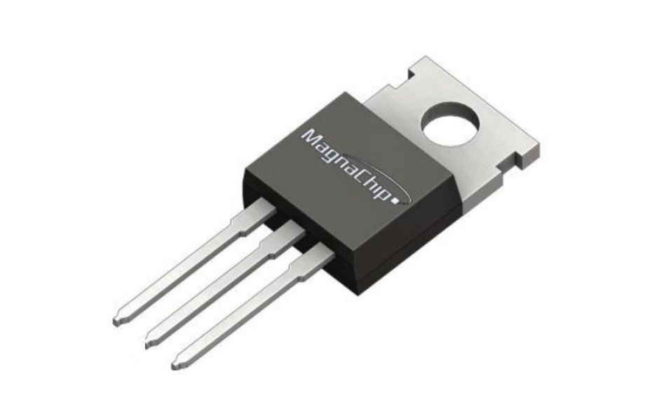
In the pic above, notice the legs are skinny at the tips, and fatter near the body of the MOSFET, because this will be mentioned again soon.
The MOSFET’s are the “on/off” switches that send power to each of the three motor phases in turn, at just the right moment. The name stands for “Metal Oxide Semiconductor, Field Effect Transistor”. The amount of amps a controller can flow is largely dependent on the size of the MOSFET’s, and the quantity of the MOSFET’s. This controller uses the TO-220 format, and it has 24 FET’s, so it uses 8 FET’s per phase.
Votol rates this controller for 150A of battery current, and 470A of phase current, which is 58A per FET. This is a reasonable rating, and it is inline with the factory spec for this FET.
[If I’ve said any part of this wrong, I apologize in advance]
______________________________________________
The Circuit Board
Normally, a circuit board is another boring component that is ignored, because…what could possibly be different or better about this one? Richard pointed out that this board is a sandwich of insulating plates, with an aluminum layer in the center. One of the reasons this was invented was to inexpensively provide some heat-spreading, and in some designs its enough to eliminate needing a separate heat-sink. It’s a “Metal-Core Printed Circuit Board” / MC-PCB. This begs the question, do any other controller models use a MC-PCB?

Votol’s engineers selected this type of MC-PCB, which is brilliant! Of course the controller has a fat aluminum baseplate as a heat sink, but this aluminum PCB-core is a middle-man that prevents localized hot-spots from forming.
______________________________________________
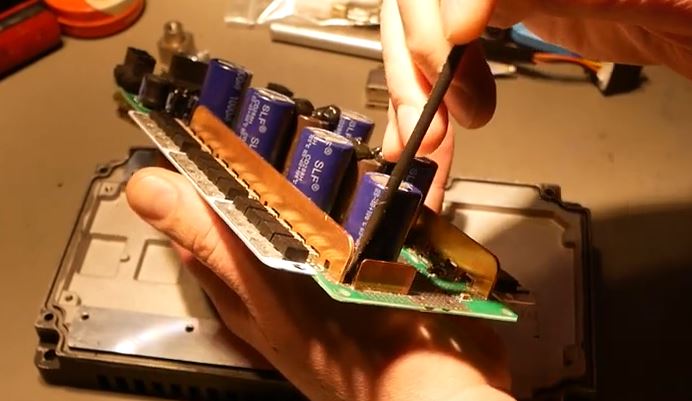
The Battery Plus and Minus Buses
These buses are another area where the Votol shines.
According to Richard “…this one piece of copper has more material than is in all the reinforcing in like a KO-Pro, or a [Sur-Ron] F-Spec power stage. Because this is…two and a half millimeters thick, and it’s one big piece, and it’s not like little sections and pieces and stuff kind of stuck down haphazardly. No, this is a custom-made part….”

In the pic above, in the foreground is the battery minus bus, a thick blade of copper.
In the pic above, Richard points out a gap that could have easily been avoided and it would have made the long section of bus and that short piece into all one piece. It does work as is, but it would have been a little better if those two were one piece, instead of them being connected by a trace on the underside of the PCB.
One of the few areas that Richard felt is lacking is the DC high-frequency filtering. The ceramic capacitors were small, and there were not enough of them. Apparently it’s adequate, but it would have not cost much to dramatically improve, which would eliminate the static “noise” that rapid switching produces. The low DC bus current is smoothed-out quite well and any ripple voltage is very suppressed.
______________________________________________
The Underside
Once you flip the PCB over, you can see the large solder-covered copper pads with the through-holes that allow the fat Phase-wire connectors to be bolted to the controller. These posts are made from fat chunks of copper as shown here being held between Richard’s fingertips. Each post is connected to the controller PCB by four bolts, so it will not rotate or come loose.

______________________________________________
The MOSFET Legs
In the pic above, Richard uses his screwdriver tip to point out how long the legs are on the MOSFET’s. The legs are tapered, and if you use the tips as a connection, they are rated for 50A, but if your design allows them to be mounted in a way that connects them at the fatter end of the leg, then the legs are rated for 70A.

This doesn’t limit how many amps you can flow through them, but it will make them run a little hotter than necessary. It’s not really something a builder can fix in their garage, because the backs of the MOSFET must attach to the heat-spreader, to connect to the heat-sink. If the heat sink was designed a little differently, the MOSFET’s could have connected at the fat end of the legs.
______________________________________________
The Conclusion
Every controller design has compromises with its pluses and minuses, and Richard has mentioned that this Votol design is overall better than the KO-Moto and the Sur-Ron F-Spec controllers.
The Good:
Fat copper buses
Aluminum sandwich PCB to prevent hot-spots near the components
Name-brand CPU and FET’s
Fat copper posts to attach the motor-phase cables to, each held down by four bolts
Heavy duty cover that is less likely to crack or break
The Bad:
Silicone gaskets for the phase wires are friction fit, but are easy to add silicone sealant to to improve moisture resistance.
The High-frequency ripple filtering capacitors are too small and there’s not enough of them (It may be “possible” to swap-in better capacitors), but…it works OK.
MOSFET’s are connected at the thin part of the leg. The current layout doesn’t allow the FET’s to be moved closer to use the fat part of the legs
_____________________________________________
Other controllers that he mentioned as being as good or better were the E-Moto, Trampa, ASI, and E-BMX. However, he pointed out the reason for the interest in the Votol is it’s price range, which makes it more affordable than the four brands he mentioned as being well-designed.
I must add that this review does not cover ANY of the programming interfaces, and I don’t know if the Votol is complex to program or easy…or…if the other controllers mentioned are comparably “user friendly”.
Also, Votol has several models of controller that are smaller than the EM-150, and several that are larger, depending on your needs for an ebike, E-scooter, or E-motorcycle.
Richard makes a good argument that the controllers that are as good as the Votol will cost more, and the ones at the same price range are not as good. Thank you Richard for doing this tear-down and posting the video on youtube!
______________________________________________
LINKS
Richard’s Youtube channel, “EV Components Review (De-bodgery)”
Votol Controllers web page (Click Here)
The Endless-Sphere chat forum discussion of Votol controllers (Click Here)
Richards Facebook page (Click Here)
______________________________________________
Written by Ron/spinningmagnets, July 2023
[ad_2]
Source link


