


[ad_1]
The methods used to build a battery pack from cylindrical cells are fairly well known, but pouch cells don’t seem to have a decent article yet, to describe the “best practices” on how to build them. I’ll do my best to show what I found when I recently did a search.
______________________________________________
Why Pouch Cells?
When you stack-up cylindrical cells, there is some airspace between each cell, and that’s wasted pack volume that could be used for more active battery material. This isn’t a huge problem for ebikes, but it’s a matter of deep concern for electric motorcycles builders.

A 52V pack that has 20-Ah of range is considered a pretty significant ebike battery pack, but that’s not enough power or range for a scooter, much less a full-sized E-motorcycle. The Zero motorcycle company uses 28S / 104V nominal, and as far as range, their smallest pack is currently 44-Ah, with larger packs available. That’s roughly four times the total energy, and most Zero E-moto owners have chosen the larger battery pack option. E-motorcycle builders need to cram as much active battery material as possible into a frame with limited frame-space.
______________________________________________
A 12V Jumpstart Box
I haven’t built an electric motorcycle, but I do occasionally need to jump-start a piece of equipment at work. I had read that the cells that put out the most amps are from hybrid vehicles. This is because EV’s that have a large battery pack (like Tesla) will be able to make more than enough amps, so…they can use cells that are optimized for long range. A hybrid EV has a back-up engine to provide long range, and that means that the expensive battery pack can be small. However, this EV hybrid pack must be able to provide full-vehicle performance from a small pack, sooo…these cells put out high amps.
I saw a youtube video where an electrician tested the amperage draw on his 4-cylinder gasoline car’s starter. In the first half-second, it drew a peak of 200A to get the motor spinning, but settled into roughly 100A to continue spinning (the spark and fuel were turned off) . He was putting together a super-capacitor jumper-box to help him start his car when the weather was below freezing, and it was able to turn over the engine for up to 8 seconds. Chemical batteries like lead-acid and lithium will lose a lot of their amp-producing capability when they get extra cold, but super-capacitors work just fine in cold weather. This is part of the reason Tesla cars have a battery warming/cooling system.
I briefly considered building a super-capacitor bank, because they can provide very high amps in a tiny package, and as stated before, they can operate well in sub-zero weather. However, super-capacitors bleed-down their voltage over time, so I would have to re-charge the super-capacitor pack just before trying to start a vehicle with a dead battery. The “filler” battery was typically a 4S Lithium-Iron pack that is pocket-sized, and even an 18V cordless tool battery can be used. It would take a few minutes to use a cordless tool pack to “fill” the super-capacitor bank (the filler battery pack is kept warm inside the house until needed). Then, you would take the super-capacitor bank out to the frozen car to help start it.

I opted for the simplicity of building my own “jumper” suitcase with only large lithium pouch cells, and no super-capacitors. This way, it would have more “range” when using it as a power back-up during a power outage (I live in tornado country, with frequent wind-storms). I wouldn’t call it small, but it is just light enough and fairly compact, so that I can store in the warm indoors. In an emergency, I can also use it to keep my phone, laptop computer, and my rechargeable USB flashlights charged. If you are considering building a large and expensive battery pack for an E-moto conversion, I recommend building a jumper box first. It will teach you everything you will want to know, before spending the big bucks on the full-sized project.
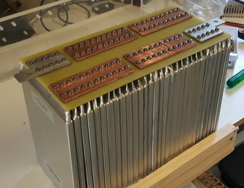
I found some threaded aluminum bars that would work, to clamp the tabs against each other (seen in the pic above). If I hadn’t found these, I was about to buy some bar stock, then cut, drill, and tap threads into them myself. Since the tabs are touching each other in this configuration, the clamping bars are not used as conductors, and could have been steel to maintain stiffness, and provide an even clamping pressure.
When using common lithium-Ion cells that are fully-charged to 4.2V per cell, three of them in series produce 12.6V. Lithium-Iron Phosphate cells (LiFePO4) run at a lower voltage, and they are fully charged at 3.6V each, so a LiFePO4 pack that is used to provide 12V is typically a 4S pack, and 14.4V when fully charged. The LTO chemistry is rare, and at 2.4V per cell, a 12V pack would have six cells in series, for 14.4V.
______________________________________________
Chris, in Perth Australia
Chris races electric motorcycles (endless-sphere forum member “jonescg”). When he started, there was nobody around to build a large battery pack for him, using a custom voltage and shape, so…he learned how to build them himself. He has tried a few different methods, and he has agreed to allow me to show them here.

The first step for the method Chris uses is to order a thick PCB (Printed Circuit Board), made to the design that he drew on a computer. PCB’s are usually used as a circuit board to attach electronic components to them, but this is a clever use of an existing product-line to use a PCB in a way in which it was never intended to be used. The hex-shapes on the bottom side of the PCB’s were chosen to make a place that threaded nuts could be soldered-to in those locations, rather than using epoxy or some other method, like rivet-nuts or thread-serts.

In the pic above you can clearly see the slots that the tabs slide through, and also the soldered nuts that the clamping screws attach to. The nuts do not require a lot of “anti-turning” hold, so soldering the edges provides plenty of strength. However, the nuts are nickel-plated specifically to make soldering easier.

I’ve seen some battery pack builders use a paper-hole punch to make a hole in tabbed pouch cells, but these cells were ordered with thicker collector-tabs for the high current that Chris needed. The “punch” is made from a rod that has had a hole drilled into it sideways. This results in a shape that works well for punching holes through his alignment jig, shown on the left.

Chris uses thick copper bus-bars to connect the tabs to each other. The pic above shows how the tabs slide through the PCB plate, and are then folded over. The actual production plates and buses have more holes than this, but Chris was eager to post a pic of a prototype. Copper buses that touch the tabs not only have low-resistance for carrying high current, they also act as heat sinks to cool the battery by pulling the core-heat out through the tabs.

Just under the head of each stainless-steel screw is a stainless split-lockwasher to provide constant compression on the tabs, during heat and vibration cycles. Then, a stainless washer is under the split-lockwasher at the bottom to spread-out the compression. This pack uses three cells in parallel, 3P.

Chris made an assembly box out of non-conductive clear acetal plastic. The pack shown above lays-out the cells in a U-shape, so the positive and negative end-terminals are both on the same end, Shown here on the left.
The pack above uses larger cells, but the same method as before. I used a similar “head-plate” configuration to make my jump-starter suitcase battery, but since I was only making one of them, I simply used a thin kitchen cutting-board that was made from HDPE / High Density Poly Ethylene, instead of a special-order PCB board.
______________________________________________
What Next?
At this stage, you would still need to attach a BMS, and a sturdy housing to protect the cells. You can see how to attach a BMS by reading here, and also we wrote a few things about what a BMS does in another article, which can be found here.
______________________________________________
Written by Ron/spinningmagnets, May2021
[ad_2]
Source link


